Garduino
 I just finished working on a prototype for a Garduino gardening project that I have been working on for a couple months, and thought it would be cool to share it’s current status, and provide a DIY reference for anyone who wants to build something similar.
Description
A few months ago I decided I wanted to build myself a self watering herb garden. What started as a simple idea to have a pot that waters itself every day evolved into an expandable project that features moisture sensors, timed lights, and self watering planters.
Rough list of Parts
- Arduino Uno
- Solenoid Valves
- Moisture Sensors
- 12v Compact Fluorescent Lights
- Plenty of wire
- Vinyl tubing
- Various plumbing connectors and clamps
- A water source (I used an old windshield wiper fluid container)
- Various resistors
- TIP122 transistors
- IRL510 MOSFETs
- 1N400x diodes
- Mounting hardware
Steps
Note that many of these steps have gone through a few iterations, so don’t take them as a definitive guide.
Step 1 – Setup the plumbing
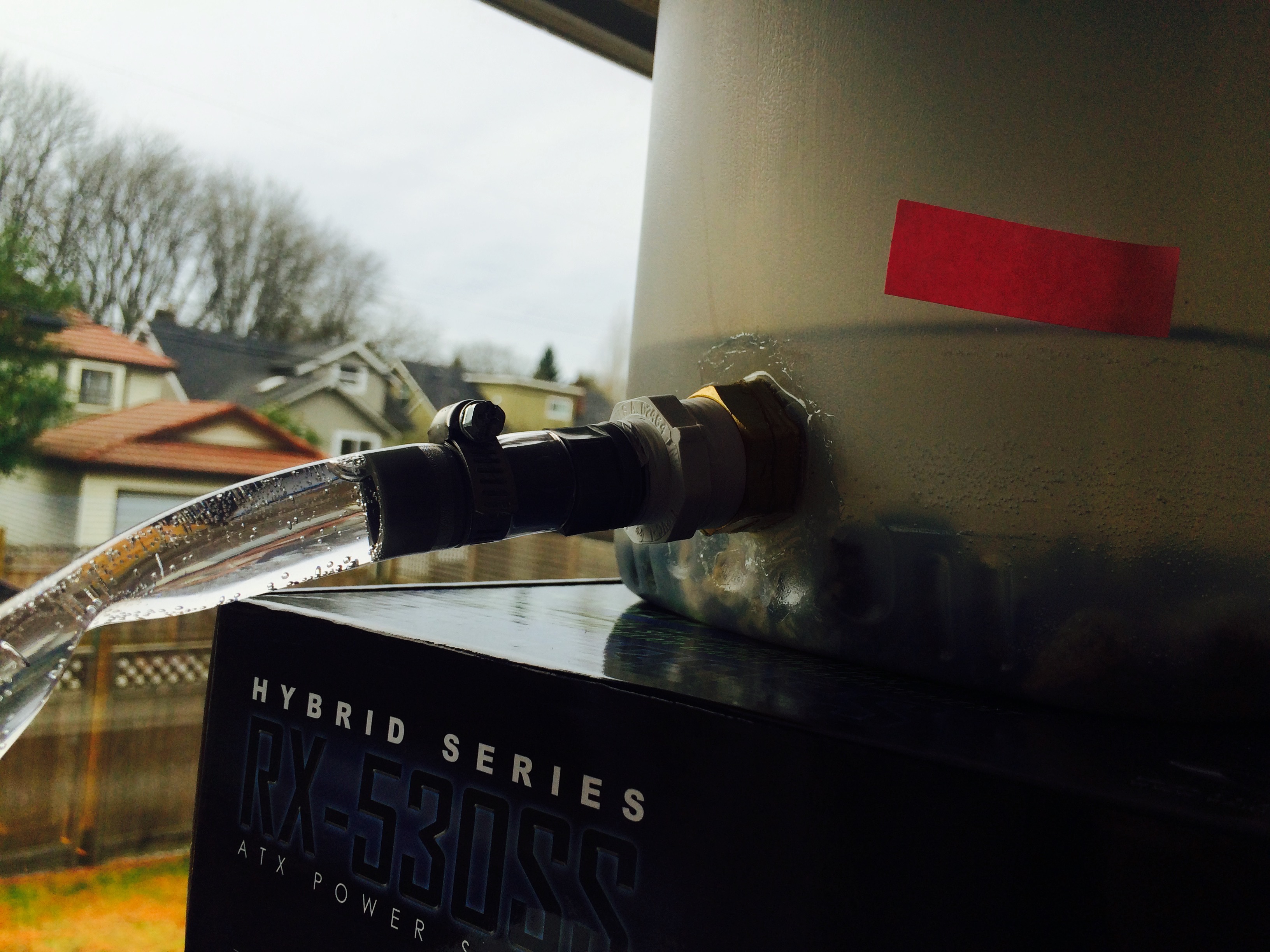
This was actually the most difficult part for me. Being a software developer by training, it took me a few tries to get something that I was happy with. I started by taking an old windshield wiper fluid container and cutting the top off. I drilled a largish hole in the bottom portion and fitted some plumbing connectors that I found at the local hardware store. I then siliconed the crap out of the inside and outside and leak tested overnight to be safe. Here is the final product:
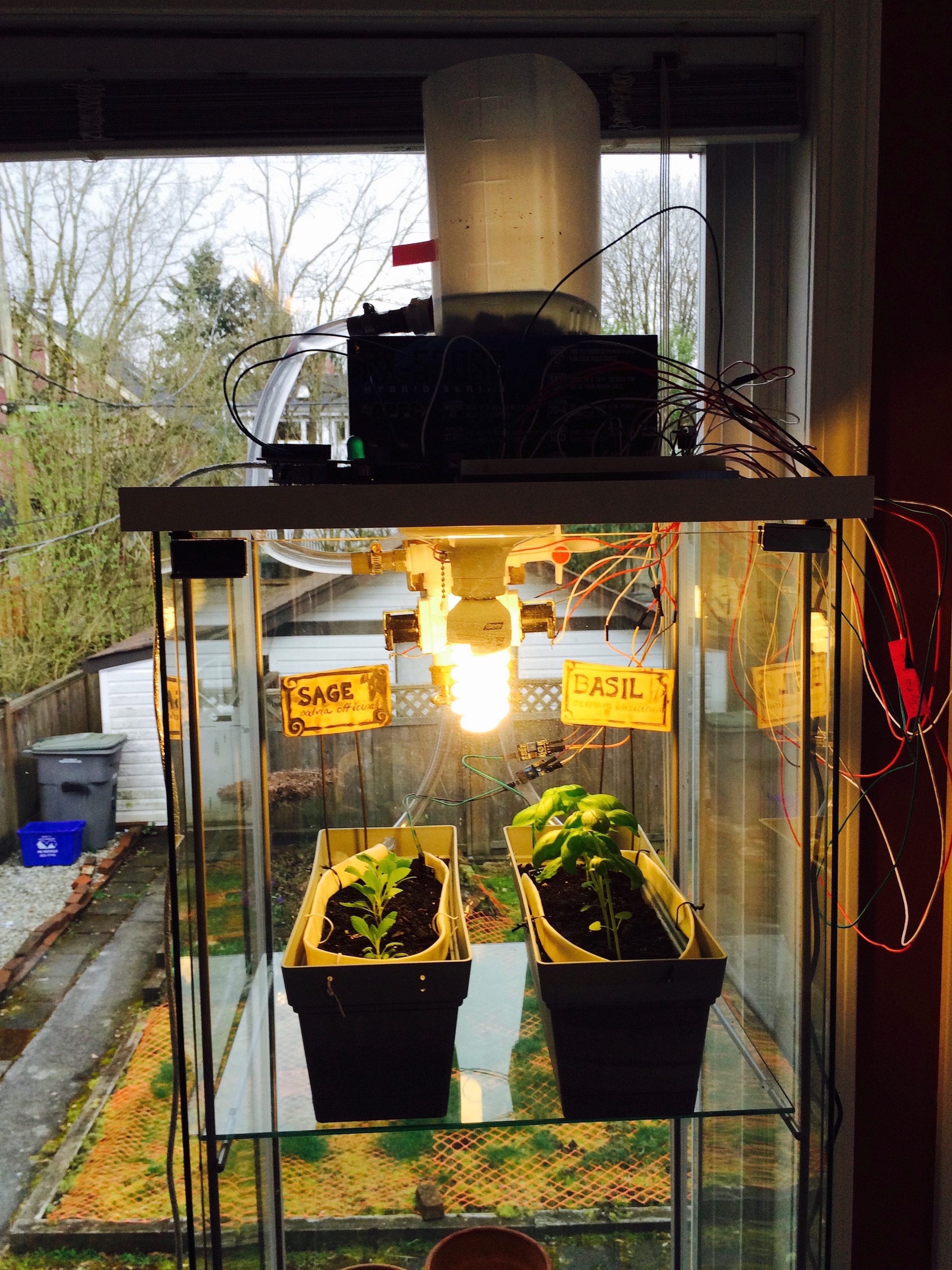
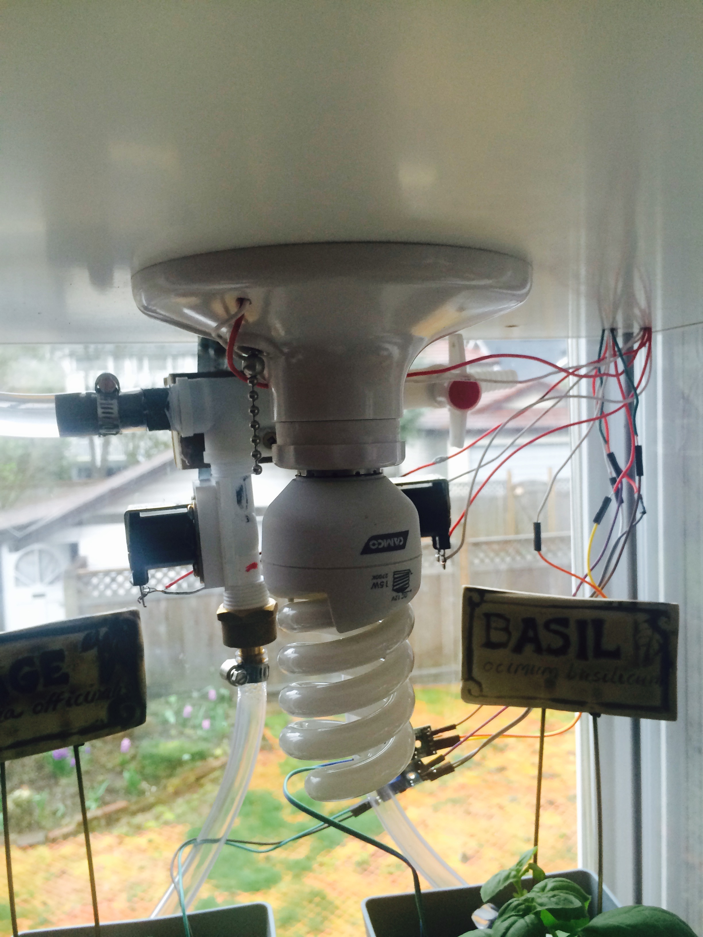
This is where you can get a bit creative. I ended up using an old IKEA cabinet with glass sides as my case. I mounted a 4 way pipe splitter to the base of the top of the cabinet, and drilled a large hole in the top piece that I could send the tubing through. The final result looks like this:
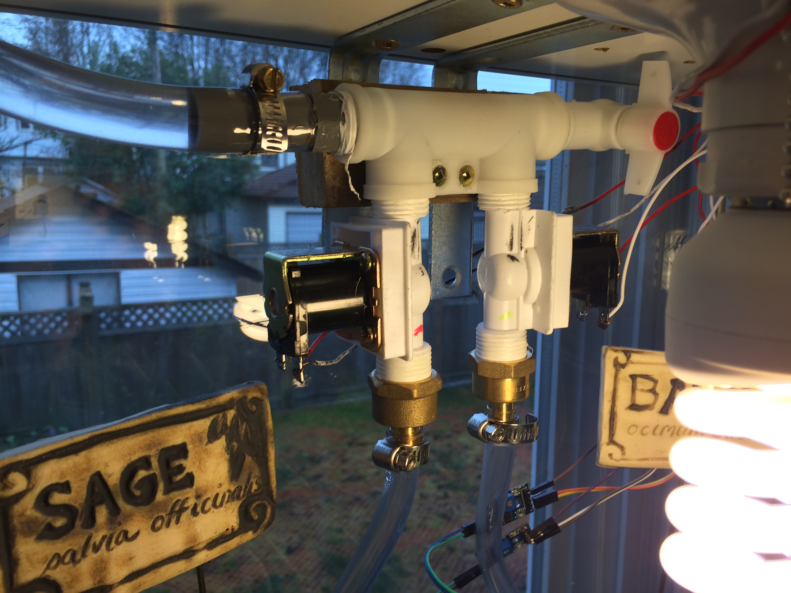
At this point, I screwed my two solenoid valves into the splitter, and ran tubing from the valves down into the plants. The trickiest part was getting an even distribution of water over the plants. I ended up poking holes into one side of the tube with a nail, and sealing the end with silicon. When the valves are open, there is enough pressure that water sprays out from the holes into the middle of the pots, all over the plants.
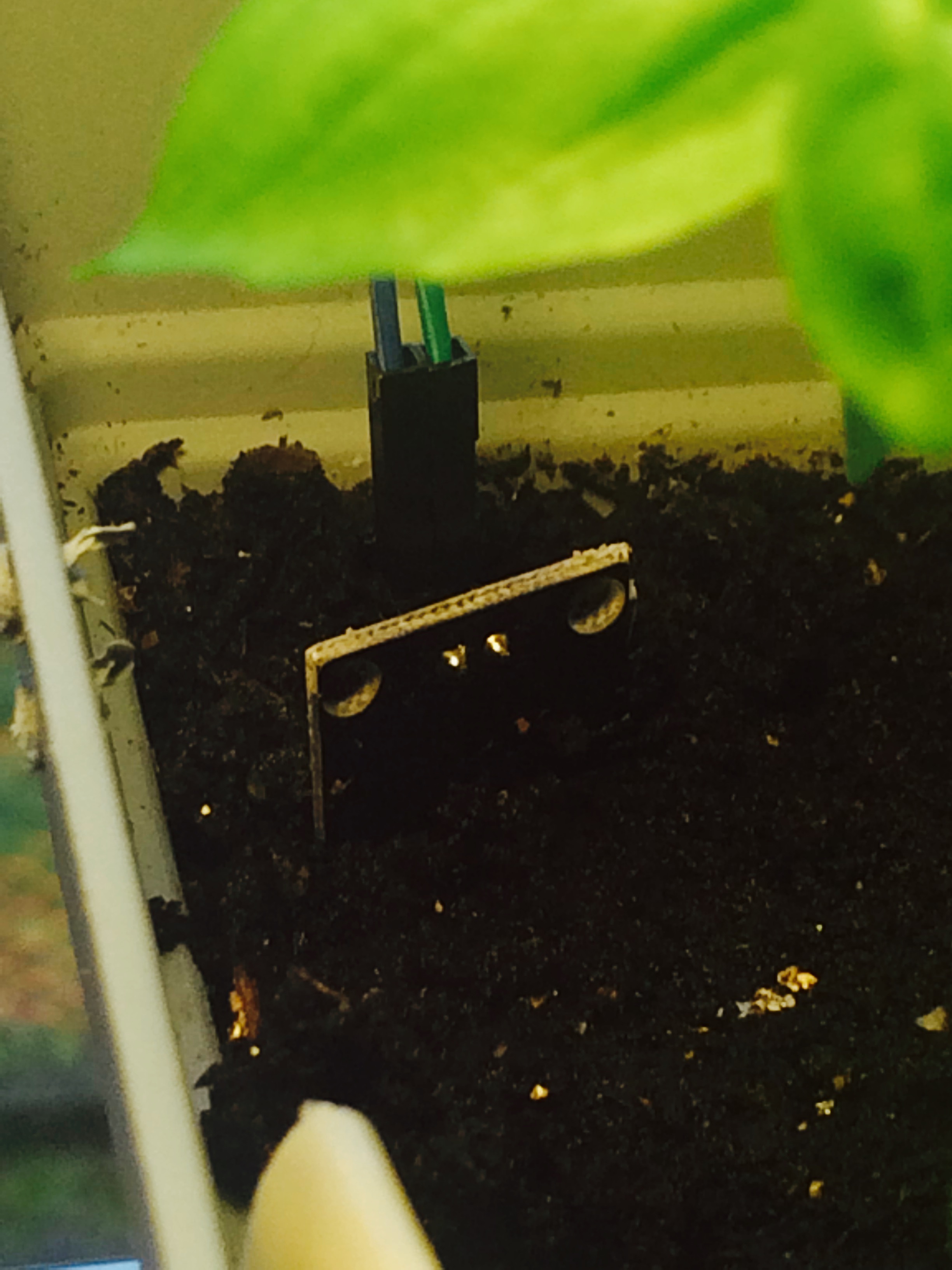
Step 2 – Setting up the moisture sensors
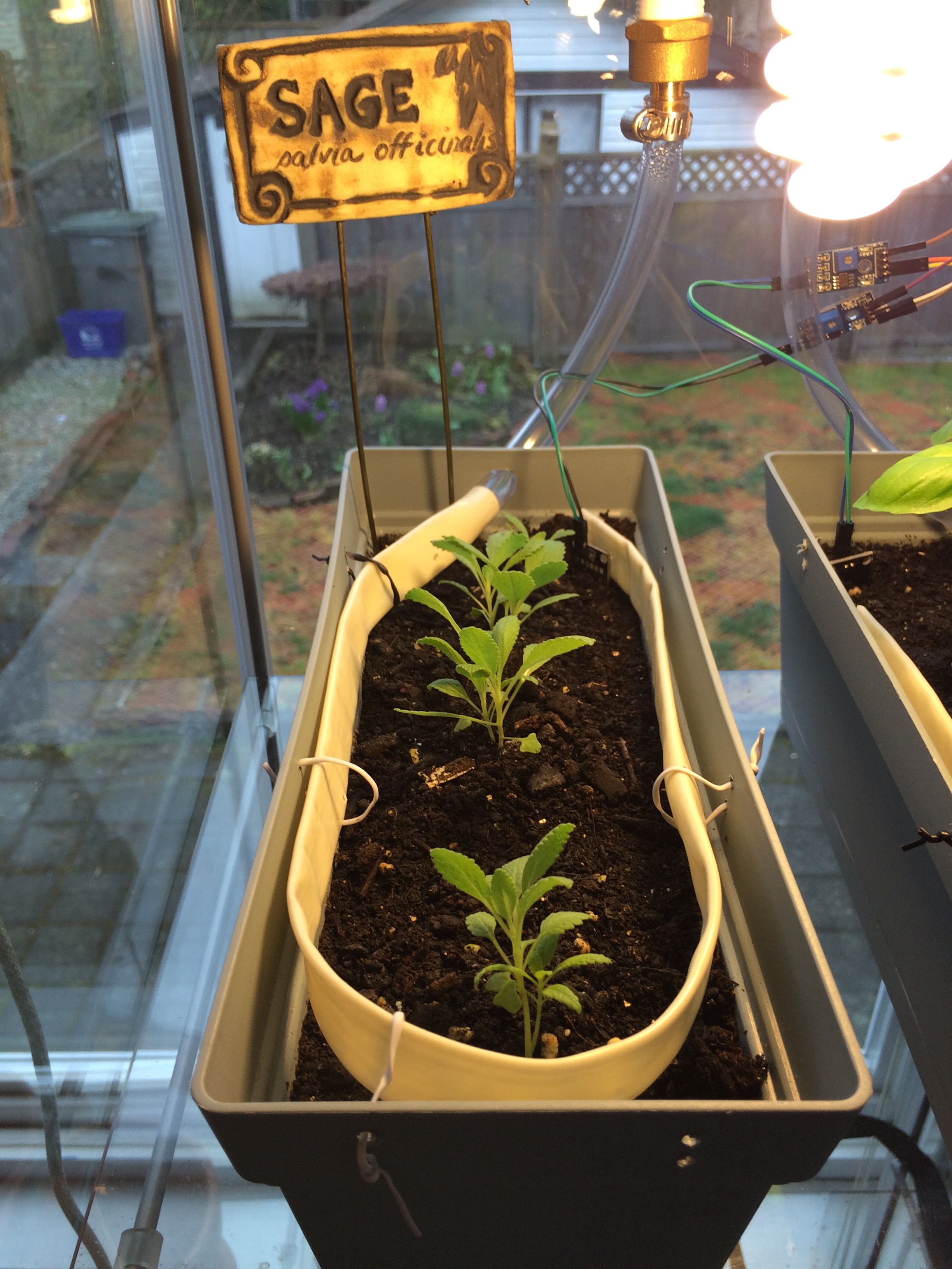
Once I had the tubing setup, I added the moisture sensors. I just bought cheap sensors from a local DIY electronics store, but I am debating getting some higher quality sensors as the cheap ones are prone to rusting. The premise of the sensors is simple – when the sensors read a moisture level that is below some threshold, open the valves and water the plants. There are quite a few edge cases that need to be accounted for in the code, but the general idea is easy to implement. Here is how the sensors are setup:
Step 3 – Add the lights
Initially, I had no plans to include a lighting mechanism in the project. Being in dark and dreary Vancouver, however, I ended up realizing that my plants would die if I didn’t give them a bit of artificial light. I wanted to avoid using mains electricity as 120v and water didn’t seem like a good combination. I ended up finding some 12v fluorescent lights online that connect to standard light sockets. I went to the hardware store and purchased a few cheap basement socket mounts, and mounted one to the top of my IKEA case.
Step 4 – Wiring everything
This is another area where I really struggled. Not having taken physics since high school, my electrical engineering knowledge is severely lacking. After running my schematics through various people who knew what they were talking about, I ended up with this:
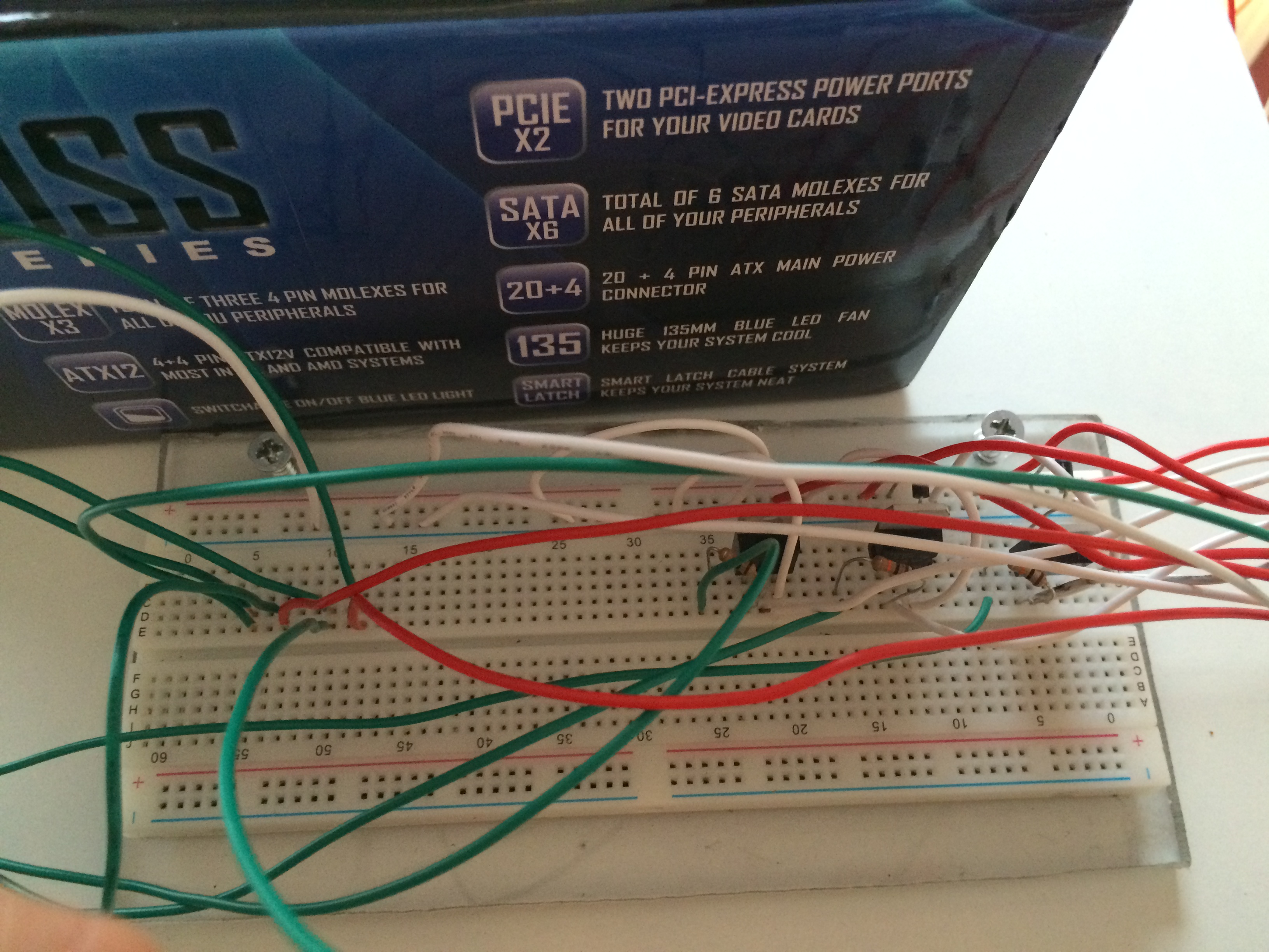
There are a few important things here:
Solenoid valve wiring:
As solenoids are prone to voltage spikes, it is critically important that you use a flyback diode in the circuit. As can be seen in the below image, I am using a transistor to control the 12v solenoid valve from the 5v output pins of the Arduino. I connect a digital output pin from the Arduino to the Base pin of the transistor, through a resistor. The Collector pin of the transistor is connected to the solenoid ground. The collector pin also has the flyback diode going to the circuit power line. The Emitter pin of the transistor is connected to the circuit ground. When I power the digital out pin of the Arduino, the transistor will allow current to pass through and the solenoid valve will open.
INSERT PICTURE HERE
Light wiring:
The light wiring is identical to the solenoid valve wiring, minus the diode as there is no voltage spike potential. I used a MOSFET for this instead of a transistor, but it doesn’t really matter which you use.
INSERT PICTURE HERE
Moisture Sensor wiring:
As the moisture sensors operate at 5v, I used the 5v out from the Arduino to power them. Instead of powering the sensors 24/7, I hooked them up to the Arduino digital out pins to preserve some life and keep them from rusting so quickly. Instead, I turn them on every hour and take a few readings, instead of leaving them on all the time.
INSERT PICTURE HERE
Step 5 – Coding
This was the easy part for me. Here is a link to the code: Github Link
Conclusion
So far, the system is working great. I have been growing sage and basil in it from their seedlings stages, and they are still doing well 2 months after potting them. I also designed and coded with expandability in mind. In order to add new plants, I just need to go out and get a new valve, and add a new plant into the code. If you have any questions about the project, feel free to comment or send me a message using the contact page.